
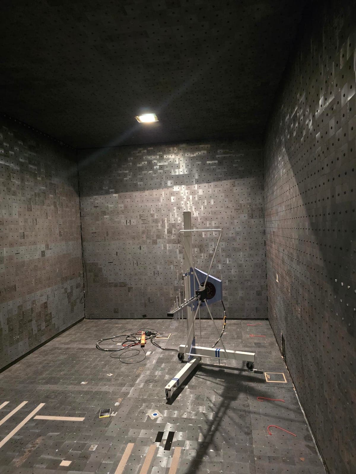
Measuring radiated emissions
We measure the emissions of your device – radiated and conducted – and place the values against the relevant limits. For radiated measurements the fully anechoic chamber in Harbke covers a frequency range up to 10 GHz.
- Service
- Measuring radiated emissions and putting them into context
- Location
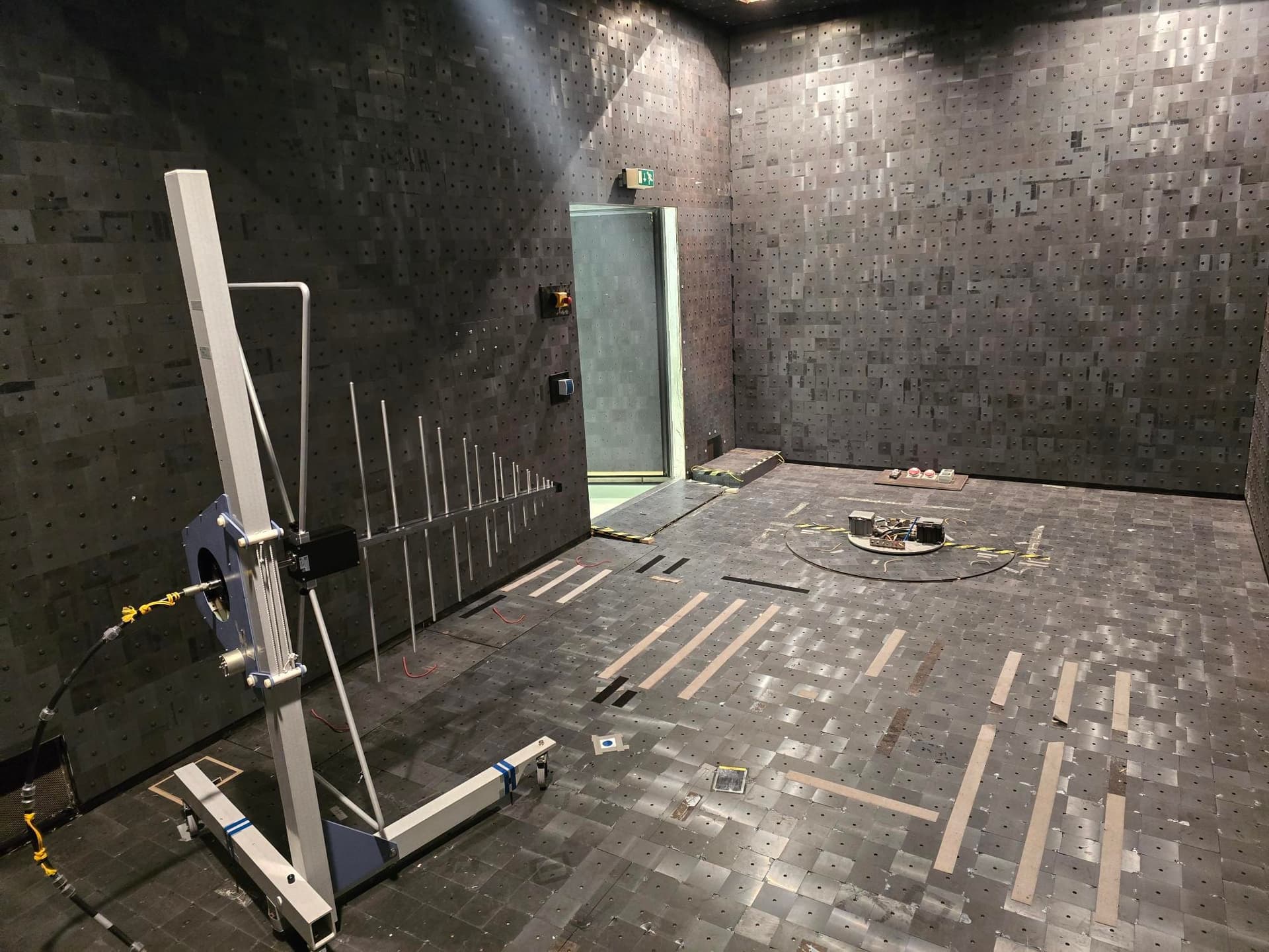
- Fully anechoic chamber, Harbke
- Frequency range
- up to 10 GHz, antenna distance up to 3 m
- Result
- Measurement data, assessment and critical frequency ranges
Two test environments. One shared EMC capability portfolio.
Our two test environments together form the EMC capability portfolio of EMC Labs. The appropriate environment and test setup depend on the test method, device under test, supply requirements, setup and engineering question.
Emissions
- radiated emissions
- conducted emissions
Immunity
- radiated immunity
- conducted immunity
- ESD
- surge and burst
Diagnostics and optimisation
- near-field investigations
- root cause analysis
- verification of optimisation measures
These capabilities are provided across our two test facilities. The appropriate facility and test setup are selected for each project.
Request the right test environmentBefore you enquire
Will your device fit our measurement environment?
These seven points decide whether we can measure your device in Harbke and how the measurement day will run. It is best to clarify them before enquiring – whatever is open, we go through together.
Not yet sure whether emissions are what needs measuring at all? Emissions or immunity – which do I need? sorts the two directions by the symptom you are seeing.
Dimensions
Height, width and length including the setup and the supply lines. The chamber dimensions are 4 × 4 × 8 m (H × W × L) – how much of that the device can occupy depends on the setup, the cabling, the peripherals and the measurement distances required.
Power supply
Which voltage and current does the device need? Available are DC 0–60 V, up to 10 A and AC three-phase, up to 32 A.
Operating states
Which states should be measured – idle, full load, communication, start-up? Each state is a measurement of its own.
Peripherals
Whatever the device needs in order to work: loads, counterparts, controllers, cooling. Bring what belongs to it.
Cables required
Number, length and type of cables shape the result considerably. We document the cable routing so the measurement stays repeatable.
Frequency range
The frequency range of the chamber extends up to 10 GHz and the antenna distance is up to 3 m. Which range matters for your product follows from the product standard.
Transport and setup
How does the device get into the chamber, is lifting equipment needed, how long does the setup take? We plan that in advance.
Technical data sheet
Fully anechoic chamber, Harbke, Harbke site (Saxony-Anhalt, Germany).
- Frequency range
- up to 10 GHz
- Antenna distance
- up to 3 m
- Chamber dimensions
- 4 × 4 × 8 m (H × W × L)
- DC supply
- 0–60 V, up to 10 A
- AC supply
- three-phase, up to 32 A
- Apparent power
- approximately 22 kVA
The figure of 4 × 4 × 8 m describes the internal dimensions of the chamber, not the maximum size of the device under test. The size that can actually be accommodated depends on the setup, the cabling, the peripherals and the measurement distances required, and is agreed on a project-by-project basis.
We agree the test scope and the depth of assessment per project – depending on product, target market, operating states and development stage.
How a measurement runs
Define the setup and operating states
We agree with you how the device is set up, which peripherals run alongside it and which operating states get measured.
Measure and observe
Measurement of radiated emissions across the available frequency range, varying turntable and antenna position.
Narrow down anomalies
If critical frequencies appear, we follow them up right away – with near-field investigations if needed.
Put the results into context
You receive the measured values compared against the limits relevant for your product, plus documentation of the setup.
Typical use cases
- A first assessment of a prototype against the applicable limits
- Narrowing down critical frequency ranges ahead of an external test
- Comparative measurements before and after an optimisation measure
- Investigations on large devices that do not fit on a bench setup
Limits of the equipment
- The antenna distance is up to 3 m; measurements at a 10 m distance are not possible.
- The chamber dimensions are not a commitment on device size – the size that can be accommodated depends on the setup and is agreed per project.
- We measure at the pre-compliance stage. These are not accredited tests.
Related pages

Have your radiated emissions measured
Briefly describe your device, its dimensions and its power supply. We will come back to you with an assessment of a sensible test scope and a proposed date.