Root cause analysis and optimisation
An exceeded limit does not yet say where it comes from. We locate the interference source in the setup, derive concrete measures and prove their effect in a re-measurement.
- Service
- Locate interference sources, derive measures and verify them
- Location
- Meine, Harbke if required
- Verification
- Re-measurement under identical conditions
- Result
- A located cause and a verified measure
When the cause is unclear
Without a known cause, all that is left is trial and error: one more filter, a plate moved, a cable rerouted. Every round costs time, and whether a change really worked often stays open.
We work the other way round: locate first, then form a hypothesis, then measure one change after another. What comes out of it is a measure whose effect is documented.
How we go about it
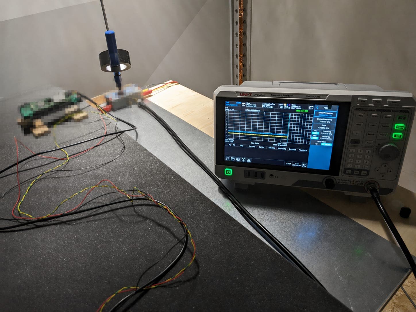
Locating is done with near-field probes on the board, the cabling and the enclosure – on a setup we can work on while measuring. At the Meine site there is a development bench next to the shielded chamber. Which test environment fits for the measurement and the re-measurement depends on the test method, the device under test, the supply and the setup.
Put the anomaly in context
We look at the measured values you have: which frequencies, which operating state, how far from the limit. That determines where the search starts.
Locate the interference source
With near-field probes we go over the board, the components, the cables and the openings in the enclosure. That turns an exceeded limit into a specific spot in the setup.
Test the hypothesis deliberately
We change individual boundary conditions – cable routing, shield bonding or filter population, for instance – and measure the effect of each change on its own.
Define the measure
We record the changes that worked as a measure, with an estimate of effort and effect. Implementation happens in your development.
Re-measure
After implementation we measure again under identical conditions, so the improvement is documented and does not rest on an assumption.
Where measures take effect
Which areas come into question in a specific case follows from the measurement – not from a standard list.
Layout and grounding
Grounding, return current paths, stack-up, placement of critical components and clock lines.
Cabling
Cable routing, separation of power and signal lines, shield bonding and connectors.
Filtering
Filters at supply and signal inputs, decoupling, attenuation of individual frequency ranges.
Shielding and enclosure
Openings in the enclosure, gaps and gaskets, bonding of shielding plates, displays and controls.
What we can commit to
We commit to narrowing down the cause with measured evidence and to naming measures whose effect we re-measure. We do not commit to a product passing a later test – that depends on the implementation, the final setup and the applicable standards.
Root cause analysis is part of development support and can equally be commissioned on its own.
Anonymised example from practice
How a root cause analysis runs
The following sequence is deliberately anonymised and free of numbers. It shows the method, not a specific customer project.
An anomaly in the measurement
A pre-compliance measurement shows clearly elevated levels in a defined frequency range. The operating state in which the effect occurs is recorded.
Locate the interference source
With near-field probes we work through the setup: board, supply lines, connectors, openings in the enclosure. The aim is to narrow down the place where the level arises or escapes.
Formulate a technical hypothesis
From the measurement pattern and the setup, a reasoned assumption emerges – for example that a cable is acting as an antenna, or that a shield bond does not make full contact.
Implement a single measure
Deliberately only one change at a time. If several measures are implemented at once, it is impossible to say afterwards which one worked.
Re-measure the effect
Re-measurement under comparable conditions: same setup, same operating states, same measurement configuration. Only then is the comparison sound.
Document the effective measure
What worked, we record with the setup, the boundary conditions and a before-and-after comparison – as a basis for your development decision and the next iteration.
Related pages
Request root cause analysis
You will receive a prompt response on the most suitable measurement option.